by Dr. Mohammad Kassemi, NASA Glenn Research Center, Mohammad.Kassemi@nasa.gov
Long-duration cryogenic storage of propellant and life support liquids is an enabling technology within the critical path of nearly all envisioned human planetary missions [1]. The pressurization and pressure control of such propellant tanks will be governed by complicated dynamic interactions amongst forced mixing, the various gravity-dependent transport mechanisms in the vapor and liquid phases, and the condensation-evaporation process at the interface. The effective implementation and optimization of a dynamic pressure control system for space applications can consequently be extremely difficult to achieve, especially without collected and relevant microgravity experimental data.
Current zero boiloff tank (ZBOT) experiments represent a series of small scale tank pressurization and pressure control experiments aboard the International Space Station (ISS). The researchers use a transparent volatile simulant fluid in a transparent sealed tank to delineate various fluid flow, heat and mass transport and phase change phenomena that control storage tank pressurization and pressure control in microgravity [2].
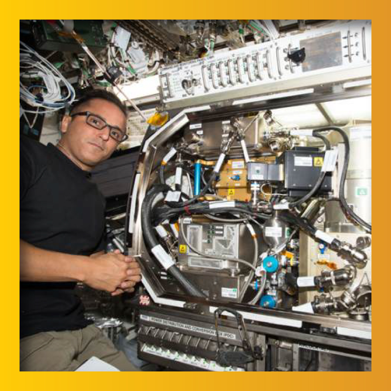
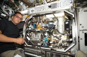
The hardware and experimental setup of ZBOT-1, the first of three envisioned hierarchical experiments, detailed in Cold Facts Vol. 33, No. 3. NASA transported the unit to ISS in 2017, where astronaut Joe Acaba handled installation within the microgravity science glovebox (MSG), as shown in Figure 1.
Close to 100 tests were then conducted over a period of roughly three months. Each test studied and quantified fluid flow and thermal stratification during self-pressurization; and mixing, thermal destratification, depressurization and jet ullage penetration during the pressure control intervals.
Hand-in-hand with the experiments, a comprehensive two-phase computational fluid dynamics (CFD) model has also been developed for simulation and prediction of storage tank pressurization and pressure control [3]. The model uses a VOF (volume of fluid) scheme to capture the fluid phases and tracks velocity, temperature and multi-component species concentrations in both domains under tight coupling with the evaporative/condensing mass transfer and energy and force balances at the phase front. The NASA team has extensively verified and validated the CFD model against both ZBOT ground-based and microgravity data, though a validation process against microgravity data continues.
Hardware and Experimental Setup
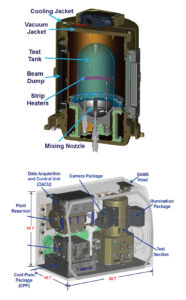
Figure 2 shows a schematic of the main components of the ZBOT-1 hardware in MSG and a cross-sectional view of the test cell made of polished optical quality cast acrylic. The test cell consists of a cylindrical midsection capped at two ends by hemispherical domes, both four inches in diameter by eight inches in height. And the device is equipped with a strip heater mounted on the outer surface of the cylindrical acrylic wall; a jet flow nozzle at the bottom that is activated during the pressure control tests; and a screened Liquid Acquisition Device (LAD) that ensures only liquid is extracted, thermally conditioned and pumped in through the nozzle during the jet flow mixing cycles.
To provide proper containment and definable and controllable thermal boundary conditions for model validation, the test cell is isolated from the MSG environment via a temperature-controlled vacuum jacket (VJ) that is also enclosed within another cooling jacket. The tank fluid temperature prior to each test and the jet flow temperatures during the mixing cycles are maintained by careful conditioning of the fluid via a counter-flow shell and tube heat exchanger in the fluid supply unit (FSU) located just below the MSG test cell.
The simulant phase change fluid used in the experiment is Perfluoro-n-Pentane (PnP, or C5F12), a non-polar volatile refrigerant with a boiling point of 29°C at 1 atm and a near zero contact angle with the test tank. NASA toxicology and ECLSS groups have approved a high purity (99.7 percent straight-chained n-isomer) version of PnP as safe for use within the ISS. A bellowed reservoir stores the fluid that is degassed on orbit initially and before each fill level change. A radial flow membrane contactor performs degassing to a high degree of purity (less than 5 torr residual gases). This process ensures that any noncondensable effects are eliminated during the ZBOT-1 tests.
Temperature-controlled windows on the VJ accommodate the camera and white light/laser sheet illumination packages included for image-capture of the ullage. This diagnostic setup also accommodates particle streaking flow visualization and particle imaging velocimetry (PIV) in the liquid region. Tank pressure and jet flow rate are measured using a high accuracy pressure transducer and a Coriolis flow meter, respectively. There are 43 RTDs embedded on a rack in the fluid, on the inside and outside surfaces of the tank wall, on the VJ and in the jet flow line and nozzle. These RTDs measure fluid and wall temperatures with a precision and accuracy that is conducive to detailed computational model validation.
Microgravity Tests and Procedures
Self-pressurization tests were conducted under three modes: VJ heating, strip heating and simultaneous VJ and strip heating; therein creating an attempt to simulate heat leaks from the environment, the support structure and both. The pressure control studies were performed either from an elevated uniform temperature condition or from thermally stratified conditions following a self-pressurization run.
Liquid was drawn from the tank, passed through the heat exchanger in the FSU and then injected into the tank at a given flow rate. This was conducted either at the average tank fluid temperature for mixing only destratification and ullage penetration studies or at a prescribed subcooled level for active cooling pressure control tests.
Jet flow rates were varied from 2 to 25 cm/s and spanned a range of jet Reynolds numbers in laminar, transitional and turbulent regimes; and a range of Weber numbers covering no ullage penetration, partial penetration and complete ullage penetration and breakup.
Particle image velocimetry (PIV) test runs were also performed to both visualize and quantify the flow fields, especially during the jet mixing operations. Since particle injection and PIV was carried out for the first time with this class of nonpolar fluids in microgravity, ZBOT tests were performed with and without particle injection to ensure both the integrity of the primary temperature and that pressure data was not compromised.
Overview of Microgravity Results
Interesting quantitative results were obtained with regard to the altered and sometimes non-intuitive microgravity behavior of fluid flow, heat and mass transfer and ullage dynamics in the storage tank, providing important implications for several aspects of storage tank design.
ZBOT pressurization data indicates that classic tank self-pressurization trends in microgravity, due to either localized or global heating, are quite similar to their 1g counterparts. However, it is also shown that both the rate and magnitude of pressurization in microgravity are lower than in 1g under otherwise similar conditions. Thus, ground-based results may be used as conservative estimates for designing the storage tank for space applications.
Such pressurization results further indicate that deviations from the classic self-pressurization trends can more readily occur in weightlessness due to microgravity thermal stratification. In microgravity, nucleate boiling of localized hot spots on the vessel wall can occur at much lower wall heat fluxes, a condition due to the weaker natural convection and thermal stratification compared to their 1g counterparts—especially if the wall also provides suitable nucleation sites.
Thus, it is envisioned that a propellant tank with a perforated internal wall structure may be subject to low intensity nucleate wall boiling, even under relatively moderate heat fluxes. Herein, a simultaneous combination of global and local heating provides the most conducive condition for microgravity nucleate boiling.
Microgravity results indicate that jet mixing during tank thermal destratification and pressure control follows a surprisingly non-intuitive trend compared to its 1g behavior. At low jet speeds (low Weber numbers) the ullage will move towards the jet nozzle inlet if the jet is not perfectly aligned with the ullage central axis. Of course, such alignment is quite difficult to arrange due to the existence of a varying 3D residual gravitational field.
At higher jet speeds (high Weber number), the ullage can be kept in the upper portions of the tank opposite the jet nozzle inlet, but will tend to move to accommodate the passage of the jet with minimal penetration. Thus, a stable ullage that can be punctured and penetrated centrally and split by the jet will be elusive, particularly at higher fill levels.
Pressure control through thermal destratification—provided by an uncooled jet entering the tank at the average tank temperature—was seen to be minimal and ineffective. However, results showed that subcooled jet mixing can serve as an effective means of tank pressure control by providing a very rapid and drastic initial tank pressure drop followed by further depressurization at a continuously decreasing rate until a steady pressure level is achieved.
A very non-intuitive and surprising phenomenon involved an immense phase change at the screened LAD. It occurred during subcooled jet mixing, where the entire test cell was filled initially with small, but subsequently growing and coalescing bubbles. It was shown that during subcooled jet mixing, the sudden drop in tank pressure—as the cold jet surrounds and isolates the ullage from the rest of the tank—causes a similar sudden decline in the saturation temperature.
It is postulated that massive nucleate boiling can be instigated at the numerous nucleation sites on the LAD screen as the saturation temperature drops below the LAD temperature. If this hypothesis is true, it implies that a liquid jet (one that selectively isolates the ullage from other hotspots in the tank to provide an effective and rapid pressure control) may still not be a suitable means of tank pressure control in microgravity due to the possibility of instigating intense boiling/phase change at other locations in the tank.
CFD model validation against ZBOT microgravity data is continuing with good success. The useful and pertinent results of the experiment have underscored the value of such subscale simulant fluid ISS-class experiments for model validation. It has also demonstrated its effectiveness for gaining a better understanding of the intricate transport and phase change interactions that control tank pressurization and pressure control while pointing out serious practical implications that may prove important to future large cryogenic storage tank design for space applications.
References
[1] J. Salzman, “Fluid management in space-based systems,” Proceedings of the Engineering, Construction, and Operations in Space, 5th International Conference on Space, Vol. 1, 1996.
[2] S. Barsi and M. Kassemi, “Investigation of Tank Pressurization and Pressure Control—Part I: Experimental Study,” ASME Journal of Thermal Science & Engineering Applications, Vol. 5, No 2, December 2013.
[3] M. Kassemi, O. Kartuzova, S. Hylton, “Validation of Two-Phase CFD Models for Propellant Tank Self-Pressurization: Crossing Fluid Types, Scales, and Gravity Levels,” Cryogenics Vol. 89, January 2018.
Acknowledgement
Funding from the ISS Microgravity Physical Sciences Program, NASA HQ, tireless efforts by William Sheredy, ZBOT Project Manager, and Dr. R. Balasubramaniam, ZBOT Project Scientist, and CFD work by ZBOT Science Team, Sonya Hylton and Dr. Olga Kartuzova, are gratefully acknowledged.